


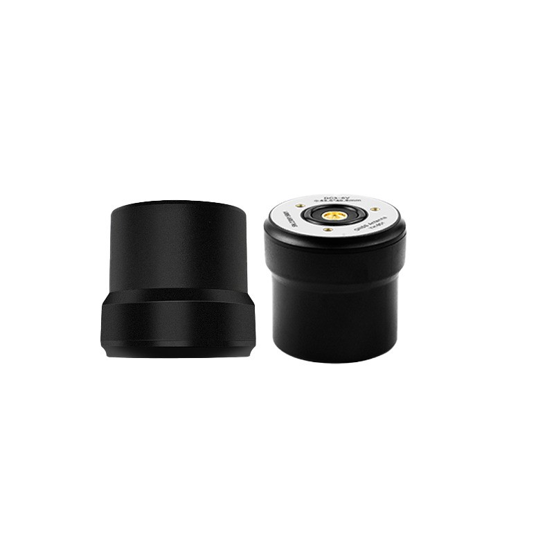
The ground plane problem, and why a small chassis changes the antenna you need
Choosing an rtk gnss antenna for robotics is constrained by a factor that does not exist in surveying: the robot has no room for a proper ground plane. A survey antenna sits on a large metal plate and looks at open sky. A robot antenna sits on a plastic shell, a few centimetres above a battery, next to a lidar, and below a payload. The same antenna that performs beautifully in a datasheet can lose half its usable gain in that arrangement.
This guide covers how the robot chassis affects antenna behaviour, how to choose between patch and helical elements for different robot types, how to handle dual-antenna heading on a small platform, and which integration details determine whether positioning stays stable after the robot has been in service for a year.
Why a Robot Antenna Is a Different Design Problem
Four constraints separate robotics from every other RTK application.
- Ground plane is small or absent. Most robot shells are plastic or carbon fibre. Without a metal plane, the antenna's pattern tilts upward, low-elevation gain collapses, and the phase centre becomes sensitive to whatever is underneath.
- Height above ground is low. An antenna 40 centimetres above the floor sees reflections from the floor itself, from walls, and from nearby equipment at angles a survey antenna never experiences.
- The platform moves unpredictably. Sudden acceleration, rotation, and vibration change the local multipath environment continuously, so stability under motion matters more than peak accuracy at rest.
- Interference is onboard, not external. Motors, drivers, and DC-DC converters radiate close to the antenna, which is a very different problem from an external jammer.
Solving the Ground Plane Problem
There are three practical approaches, and choosing the wrong one is the most common reason a robot's GNSS performance disappoints.
Approach one: provide a real plane
Add a metal plate under the antenna, bonded to the chassis and sized to at least the diameter the antenna was designed for. This is the most reliable option and the one most often skipped because it adds mass. A thin aluminium plate of the correct diameter adds far less weight than most teams assume, and it converts the antenna back into the device the datasheet describes.
Approach two: choose an antenna designed for a small plane
Some antennas are characterised on a small ground plane and are tuned accordingly. Their gain figures look lower, but they hold their pattern on a compact chassis. Matching the antenna to the plane you actually have is better than forcing a large-plane antenna into a small installation.
Approach three: use a helical element
A helical antenna does not depend on a large ground plane in the same way a patch does, and its wide beam tolerates motion and a partially obstructed sky. For small mobile robots, a helical element is frequently the more practical choice, at the cost of somewhat lower multipath rejection than a choke ring design.
Patch or Helical: Matching the Element to the Robot
| Robot class | Suitable element | Reason |
|---|---|---|
| Outdoor AGV and yard robot | Patch on metal plate | Adequate space, stable platform, better multipath control |
| Small delivery or inspection robot | Compact helical | No room for a large plane, wide beam compensates |
| Quadruped or legged robot | Compact helical, high isolation | Constant attitude change, limited mounting surfaces |
| Agricultural or field robot | Dual patch with rigid baseline | Heading at standstill, good multipath rejection |
| Indoor-outdoor hybrid | Compact patch with matched small plane | GNSS used only in transition zones |
The table is a starting point, not a rule. The decisive question is how much mechanical space the design will actually commit to. An antenna chosen for a plane that the mechanical team later shrinks will not perform as specified, and the loss usually appears as slower convergence rather than as an obvious failure.
Dual-Antenna Heading on a Small Platform
Heading accuracy from a dual-antenna antenna for robotics depends on the baseline length and the rigidity of the structure between the two elements. On a small robot, the achievable baseline might be 40 centimetres rather than the three metres available on a truck, and heading noise scales accordingly.
Two practical consequences follow. First, the mounting structure must be as rigid as the robot allows; a fibreglass shell that flexes under acceleration will inject heading error that no receiver can correct. Second, the heading output needs filtering, and the fusion filter should be told the true baseline and the expected noise so it can weight the measurement correctly.
Where the baseline cannot be lengthened, an alternative is to use the GNSS heading only as a coarse reference and rely on a magnetometer or visual system for high-frequency orientation. That combination is common in indoor-outdoor robots that only see satellites part of the time.
Multipath From the Robot Itself
The largest reflector on a robot is usually the robot. A lidar tower, a payload frame, a camera mast, or an operator handle all sit within a metre of the antenna and all reflect GNSS energy back into it. The resulting multipath has a short delay, which makes it harder to reject than the long-delay multipath from distant buildings.
The mitigation is geometric: keep the antenna at the highest practical point, with a clear hemisphere above it, and avoid placing metal structures within a quarter wavelength of the element at the lowest operating frequency. On a compact robot that is often impossible, so the practical rule is to prioritise the frontal hemisphere where the sky is actually visible during operation.
Vibration, Washdown, and Onboard Interference
A robot antenna experiences continuous low-amplitude vibration from motors and drivetrain, plus occasional shock from kerbs and thresholds. Connector retention and cable strain relief matter more than the housing strength in most designs, because the failure appears as an intermittent signal that is difficult to reproduce on a bench.
Ingress protection depends on the application. A warehouse AGV needs dust protection; a field robot needs rain and washdown protection; a food-handling robot may need chemical resistance. An IP67 rating covers immersion but says nothing about chemical attack, so the housing material has to be selected for the actual cleaning regime.
Onboard interference deserves a specific test. Run the robot with all motors at full load and compare satellite tracking against the idle condition. A drop in tracked satellites or in carrier-to-noise ratio when the drive is active indicates coupling that filtering, cable routing, or antenna placement has to solve.
Yonghao Innovation Antennas for Robotic Platforms
Yonghao Innovation Tech is a national high-tech enterprise established in 2014, based in Shenzhen, Guangdong, China. We integrate research, manufacturing, and sales, and we supply GNSS satellite antennas, positioning terminals, data communication products, and customized high-precision BeiDou solutions for surveying and monitoring, aerospace, communication time service, autonomous driving, machine control, and intelligent transportation.
Our RTK GNSS antenna range includes compact models suited to robot chassis. The YH-502 is a four-constellation full-band helical antenna with a small footprint and light weight, which suits platforms where a large ground plane is unavailable. For designs that can accommodate a patch element, the U100 provides a compact alternative within the same family.
The wider helical antenna family covers high-dynamic applications where attitude changes constantly. Typical robot configurations are described on our robotics project page, and where the chassis requires a different connector or a reduced housing height, our product customization team reviews the mechanical constraint before design changes are proposed.
Conclusion
An rtk gnss antenna for robotics succeeds or fails on the mechanical arrangement around it. The ground plane, the height above the floor, the proximity of the robot's own metal structures, and the rigidity of the heading baseline decide most of the outcome. Select the element that matches the space you can actually provide, verify the assembly with the motors running, and confirm the heading noise on the real chassis rather than on a test fixture.
Send us your chassis drawing and mounting height, and we will recommend an element and plane arrangement that fits.
Review my robot chassis See helical optionsFrequently Asked Questions
Q1: What size ground plane does an rtk gnss antenna for robotics need?
It depends on the element. A patch antenna needs a plane sized to its design diameter, which is often larger than a small robot can provide. Where that space does not exist, a helical element or a patch characterised on a small plane is the better choice.
Q2: Is a helical or patch rtk gnss antenna for robotics better?
Helical suits small platforms, constant motion, and limited ground plane. Patch suits larger platforms with a stable mounting surface, where better multipath rejection is worth the size. The decision follows the mechanical design, not the other way around.
Q3: How long a baseline does an rtk gnss antenna for robotics need for heading?
Longer is better, but rigidity matters more than length. A 50-centimetre baseline on a rigid frame gives more stable heading than a one-metre baseline on a flexible shell, because flex is indistinguishable from rotation at the antenna.
Q4: Why does an rtk gnss antenna for robotics lose satellites when the motors run?
Motor drives and DC-DC converters radiate broadband energy that raises the noise floor at the antenna. Separation, cable routing away from power harnesses, and filtering at the receiver input reduce the effect. Onboard interference should be measured, not assumed.
Q5: Can an rtk gnss antenna for robotics be mounted inside a plastic shell?
Yes, if the shell material is RF-transparent and the antenna has a metal plane beneath it. Thick or metallised plastics, carbon fibre, and painted surfaces containing metal particles will attenuate or detune the antenna and should be avoided in the mounting area.